
Uses of Leveling And Principles of Differential Leveling
In this article I have a topic related to geodesy. Uses of leveling and leveling. The use of leveling and the principle of differential leveling The use of leveling the principle of differential leveling.
Uses of The Leveling
1. In the tidal measurement environment, leveling is used for the following purposes.
2. To isolate the initial movements, there must be at least three identical marks and the leveling must be repeated periodically or semi-annually.
3. Connecting to GPS way-points To determine its natural stability and to separate the altitude of the ocean position from the instability of the earth’s crust, the TGBM must be connected via GPS to the stations fixed reference in a globally corresponding reference system.
4. In general, it is not possible to place the GPS antenna directly on the TGBM and the GPS way-point must be established a short distance away.
5. This leveling must be connected to a temporary benchmark.
6. Connection to national leveling network Mean ocean position is used to define orthogonal features for public surveying and mapping – therefore the TGBM must be connected to the public leveling network add.
7. Connecting to the network will also allow all tide gauges to be interconnected, providing information on spatial variation in the mean position of the ocean.
Principles of Differential Leveling
Differential Balance provides a means of directly measuring elevation differences between points, some removed from stepwise measurements. horizontally above the first point and reading is taken from the intersection of the reticle with the image of the staff (reverse-b).
The same (or identical) stick is also held vertically above the replacement head and further reading is performed (aim-f).

The difference between two readings is the difference in height between two points dh = b- f If b is less than f then dh is also positive (that is, there is an increase in altitude when moving from the first point to the alternate).
This process can be repeated – the position can be moved over the alternative point and the height difference between the alternate and the third point measured using the same procedure.
Subsequent iterations will determine the elevation difference between distant points by accumulating elevation differences between intermediate (temporary) points.The distance between the location and the staff is imposed by the slope of the terrain and the clarity of the image seen by the audience. In general, the maximum observation length is limited to 50-60 m.
The sketch below shows a diagram illustrating the placement into the
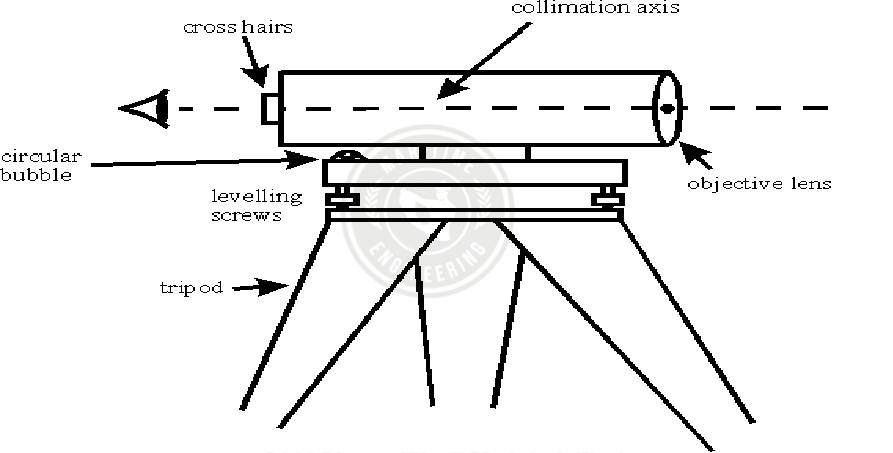
The position is mounted on a tripod and has three leveling screws (confluence with indirect bubbles) allowing the position to be leveled. These screws have a limited range and the tripod head must be pre-adjusted by adjusting the tripod pins accordingly.
The upper part of the site consists of a telescope with an objective and an eyepiece with a cell.The line of sight (collimation axis) is defined by the line connecting the center of the reticle to the focal point of the objective.
The telescope is mounted on an axis that allows it to rotate in a plane or vertical plane. Indirect bubbles are not really sensitive and are not the only way to balance positions. Older situations faced tubular bubbles that were attached to the side of the telescope and leveled this bubble using a screw foot that received a vertical line of sight along the collimation axis.
Automatic Compensator
Most modern scenarios will use any form of an automatic compensator that allows the thrower to position the device using only an indirect bubble. The figure below shows a schematic illustration of a type of compensator in this device.

The image of an object is deflected by a fixed lens as it passes through a prism, which is then deflected towards the eyepiece by another lens. The prism is suspended by a cable, and its exposure changes as the telescope lens is listed. The geometry of the instrument is designed so that any nozzle of the telescope is offset by the nozzle of the prism and the collimator remains horizontal. The cut has a limited range (lots of flashing arcs) and the position needs to be well balanced using indirect bubbles before the cut will work properly.
Related Post
Definition And Different Types Of Surveying
Useful Information on Civil Engineering
How To Calculate The Bar Bending Schedule of The Footing
THANKS
[…] Uses of The Leveling And Principles of Differential Leveling […]
[…] Uses of The Leveling And Principles of Differential Leveling […]
[…] Uses of the Leveling and Principles of Differential Leveling […]