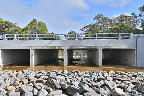
How to Calculate Bar Bending Schedule of a Box Culvert
A Bar Bending Schedule (BBS) is a comprehensive list used in the construction industry to detail the types, sizes, lengths, and shapes of steel reinforcement bars required for a particular structure. How to Calculate Bar Bending Schedule of a Box Culvert
Introduction to Bar Bending Schedule (BBS)
A Bar Bending Schedule (BBS) is a comprehensive list used in the construction industry to detail the types, sizes, lengths, and shapes of steel reinforcement bars required for a particular structure. It serves as a crucial tool for engineers, contractors, and fabricators, ensuring that the correct quantities and specifications of materials are procured and utilized.
The significance of a BBS cannot be overstated. It provides an accurate representation of the material needs, which helps in budgeting and cost estimation for construction projects. By detailing every aspect of the steel reinforcement process, a BBS allows for optimized material procurement, preventing both shortages and excesses that could lead to budget overruns or project delays.
In addition to financial efficiency, a well-prepared BBS ensures strict adherence to structural design requirements. This is particularly vital for structures like box culverts, where precise reinforcement is critical for ensuring structural integrity and longevity. The detailing within a BBS encompasses every bend, cut, and placement of the reinforcement bars, facilitating a meticulous fabrication process.
Moreover, a BBS enhances communication among various stakeholders involved in a construction project. Engineers and site supervisors can quickly understand the enumerated requirements, thereby minimizing discrepancies and misunderstandings. This clarity is essential for maintaining project timelines and ensuring compliance with safety and quality standards.
Ultimately, the Bar Bending Schedule is an indispensable document that ties together design planning, material management, and construction execution. Its detailed and systematic approach not only maximizes resource efficiency but also underpins the structural soundness of the completed project.
Components of a Box Culvert
A box culvert is an essential structure in water management infrastructure, typically designed to manage water flow under roads, railways, and embankments. It is known for its robust construction and efficient water flow management capabilities. To understand the intricacies of a box culvert, it is important to familiarize ourselves with its various components.
The primary elements of a box culvert include the slabs, walls, and haunches. The slabs consist of the top slab and the bottom slab. The top slab serves as the roof of the culvert, supporting the overlying structure such as a road or railway. It must be designed to withstand the loads imposed by traffic and other external factors. The bottom slab, on the other hand, forms the base and ensures stability by distributing the load uniformly to the ground.
The walls of the box culvert are positioned on either side, providing structural integrity and resisting lateral earth pressure. These side walls are crucial for the overall strength and stability of the structure. In addition to the primary walls, intermediate walls may also be incorporated for larger installations to further distribute the load and enhance durability.
Haunches are the elements found at the corners where the walls meet the slabs. They play a vital role in load distribution by providing a smooth transition between the walls and slabs, thereby reducing stress concentrations at these joints. The incorporation of haunches in the design significantly enhances the structural performance of the box culvert.
Box culverts offer several benefits in water management infrastructure. One of the key advantages is their ability to distribute loads evenly, which reduces the stress on individual components and prolongs the lifespan of the structure. They are also versatile, available in various sizes and materials, making them suitable for a wide range of applications. Common materials used in their construction include reinforced concrete, which provides the necessary strength and durability to withstand harsh environmental conditions and heavy loads.
In conclusion, understanding the components of a box culvert and their functions is essential for designing structures that effectively manage water flow and ensure long-term durability and stability.
Basic Formulas for Bar Bending Schedule
Understanding the essential formulas used in the Bar Bending Schedule (BBS) calculations is crucial for accurately estimating material requirements in construction projects, such as box culverts. These formulas ensure precision in the dimensions and quantities of reinforcing bars. Let’s explore the fundamental calculations involved.
Cutting Length of Bars
The cutting length of bars is a foundational element in BBS calculations. This length is determined by considering the geometry of the structure and the necessary anchorage requirements. The basic formula is:
Cutting Length = Length of Member + Development Length – Bend Deduction
Where the length of the member is the total span the bar covers, and development length is the additional length required for anchorage. Bend deduction accounts for the length reduction at bends.
Hook Length
Hooks are provided at the ends of bars to enhance bonding with concrete. The hook length, typically designed as 9d, where ‘d’ is the diameter of the bar, ensures effective anchorage. The formula for a standard 45-degree and 90-degree hook lengths are:
Hook Length (45°) = 16d
Hook Length (90°) = 24d
Bend Length
Bend length adjusts for the additional length required when a reinforcing bar curves. The standard bend allowance formula is:
Bend Length = n x (π/180) x r
Where ‘n’ is the bending angle, and ‘r’ is the radius of the bend. This adjustment is essential for maintaining the structural integrity of the steel reinforcement.
Lap Length of steel
Lapping is required when bars need to be extended beyond available lengths. The lap length ensures continuity and is generally calculated as:
Lap Length = 50d
Here, ‘d’ signifies the bar diameter, ensuring that the overlapping segments maintain adhesion and load-bearing capacity.
Unit Conversion Factors
Unit conversions are necessary to standardize different dimensions and measurements, aiding in accurate computations. Common conversions include millimeters to meters (1m = 1000mm) and kilograms to tons (1 ton = 1000 kg), facilitating straightforward integration of various components in the BBS calculations.
Accommodating Bar Diameters
Different diameters of steel bars serve distinct structural purposes. Adjustments and precise calculations for each diameter enhance the allocation of material and the overall effectiveness of the reinforcement. The formulas and corrections address the unique properties of bar diameters, ensuring structural stability.
In the sections that follow, these fundamental formulas will be contextualized in practical scenarios, providing a comprehensive understanding of bar bending schedules for box culverts.
Step-by-Step Guide to Calculate BBS for Box Culvert
Calculating the bar bending schedule (BBS) for a box culvert requires a systematic approach to ensure accuracy and compliance with construction standards. Below is a detailed guide that breaks down the process into manageable steps, ideal for both new and experienced engineers.

Reading Structural Drawings
The first step in calculating the BBS for a box culvert is thoroughly reading and understanding the structural drawings. These drawings provide detailed specifications, including dimensions, reinforcement details, and any specific construction notes. Pay particular attention to the scale used and ensure that dimensions are interpreted correctly. Identifying different sections of the box culvert – such as the base slab, sidewalls, and deck slab – is crucial at this early stage.
Identifying Steel Bar Types
Next, identify the various types of steel bars used in the construction of the box culvert. Generally, high-yield strength deformed (HYSD) bars or thermomechanical treated (TMT) bars are used. Structural drawings will detail the bar types and their placements. Common types include main reinforcement bars, distribution bars, and stirrups. Ensure you understand the designated bar marks and coding systems as indicated in the construction plans.
Calculating Lengths of Steel Bars
With the bar types identified, the next step involves calculating the lengths of these steel bars. This includes accounting for bends, hooks, and overlaps as per the design specifications. Each segment of the culvert (base, wall, and top slab) will have specific requirements. Use standard formulas to convert drawing dimensions into actual steel bar lengths, considering any allowances for overlaps and bends.
Calculating Weights of Steel Bars
After determining the lengths, calculate the weights of the steel bars.
The formula to calculate the weight of a steel bar is
Weight (kg) = Diameter^2 (mm) x Length (m) x 0.006165.
Apply this formula for each bar and tabulate the results. Ensure proper unit conversions where necessary. The cumulative weight helps in preparing the procurement list and assists in logistics and budgeting for the project.
Compiling the Bar Bending Schedule
Finally, compile all this information into a coherent Bar Bending Schedule. This document should detail each bar’s type, size, length, number, weight, and position within the box culvert. Accuracy in this schedule is crucial, aiding in material management and reducing waste. Use software or manual methods to prepare the BBS, ensuring clarity and comprehensiveness.
Illustrations or diagrams of box culvert drawings can vastly aid in understanding and validating the BBS. Accurate and detailed BBS ensures smooth project execution, aligning with structural safety and integrity standards.

Example
Calculating BBS for a Small Box Culvert
To illustrate the calculation of the Bar Bending Schedule (BBS) for a small box culvert, we will consider an example with defined dimensions and specifications. Let’s assume a box culvert with the following dimensions:
Given Data
- Internal width (W): 1.5 meters
- Internal height (H): 1.5 meters
- Length (L): 3 meters
- Thickness of top and bottom slabs (T): 0.2 meters
- Thickness of side walls (T): 0.2 meters
Now, we need to calculate the BBS for it. BBS requires determining the lengths of the steel bars needed for the top and bottom slabs, the side walls, and the diaphragm walls. The following steel bar diameters will be used:
- Top and bottom slabs: 12 mm diameter bars
- Side walls: 10 mm diameter bars
Let’s begin with the top and bottom slabs:
Top and bottom slab calculations (12 mm bars)
For the top slab, we’ll place bars at 200 mm intervals. Needed length per bar will be:
Number of bars = (3,000 mm / 200 mm) = 15 bars
Total length per bar = 1,500 mm + (2 * 0.2 m) = 1,500 mm + 400 mm = 1,900 mm/bar
Total length required = 15 bars * 1,900 mm = 28,500 mm or 28.5 meters.
Side wall calculations (10 mm bars)
- For both side walls:
Number of vertical bars = (1,500 mm / 200 mm) = 8 bars
Total length per bar = 1,500 mm + (2 * 0.2 m) = 1,900 mm/bar
Total length required for one side wall = 8 bars * 1,900 mm = 15,200 mm or 15.2 meters.
As there are two side walls, total length = 15.2 meters * 2 = 30.4 meters.
Left Diaphragm Wall Calculations
For diaphragm walls:
Assuming diaphragm walls have similar bar arrangements:
Number of horizontal bars = (3,000 mm / 200 mm) = 15 bars
Total length per bar = 1,500 mm + (2 * 0.2 m) = 1,900 mm/bar
Total length required for diaphragm wall = 15 bars * 1,900 mm = 28.5 meters.
Overall, each component’s steel bar requirement will be aggregated to understand the total quantities needed. The above example simplifies the process but showcases vital elements in calculating lengths and BBS for specific structures like a small box culvert.
Example
Calculating BBS for a Large Box Culvert
Calculating the Bar Bending Schedule (BBS) for a larger box culvert, particularly one with more intricate specifications, necessitates a detailed approach. This example illustrates the step-by-step BBS calculations, starting with determining bar lengths and subsequently calculating the total steel quantities required for structural reinforcement. Additionally, considerations for potential extra features, such as haunches, are included to provide a comprehensive understanding.
Firstly, consider a large culvert with internal dimensions of 5 meters width, 4 meters height, and 10 meters length. The wall and slab thicknesses will be taken as 300mm. The reinforcement consists of main reinforcement bars of 20mm diameter and distribution reinforcement bars of 16mm diameter.
For the top slab, we calculate the length of main bars as follows:
Main bar length = Internal width + (2 x development length) + (2 x cover length)
Assuming a development length of 500mm and cover length of 50mm, the length of one main bar is:
Main bar length = 5000mm + (2 x 500mm) + (2 x 50mm) = 6100mm
Total number of main bars can be calculated assuming a spacing of 150mm:
Total number of main bars = Culvert length / spacing + 1 = (10000mm / 150mm) + 1 ≈ 67 bars
For the distribution bars:
Distribution bar length = Culvert length + 2 x cover length = 10000mm + 2 x 50mm = 10100mm
Assuming a spacing of 200mm, the number of distribution bars is:
Total number of distribution bars = Culvert width / spacing + 1 = (5000mm / 200mm) + 1 ≈ 26 bars
For the walls and bottom slab, a similar approach can be used to determine the length and quantity of both main and distribution bars. Special features like haunches require additional calculation steps. For example, a haunch with a 45-degree angle and an additional steel arrangement needs precise geometric measurements for accurate BBS.
By following these detailed calculations, you ensure that the BBS reflects the structural requirements of a large, intricate box culvert, ensuring safety and efficiency in construction practices.
Common Mistakes to Avoid in BBS Calculations
Bar Bending Schedule (BBS) calculations are critical to the structural integrity and financial efficiency of box culvert construction projects. Yet, numerous common mistakes can undermine these calculations, resulting in compromised structural quality and increased project costs. Raising awareness about these frequent errors is essential to ensure the reliability of the BBS.
A significant and recurring mistake in BBS preparation is the incorrect calculation of bar lengths. Given the intricacies involved in measuring and cutting, it is not uncommon for errors to occur. Incorrect bar lengths can lead to either wastage of materials or shortages that may affect the project’s progress. It is crucial to meticulously verify each calculation and measurement, considering factors such as overlaps and laps, to avoid these inaccuracies.
Another prevalent error is overlooking bending deductions. When steel bars are bent to fit into the culvert design, their lengths effectively change. Failing to account for these changes can lead to significant discrepancies in the BBS. Ensuring precision requires understanding the bending formulae and applying them correctly to adjust the bar length accordingly.
Misinterpreting design drawings is an additional area where mistakes frequently arise. Design drawings serve as the blueprint for BBS calculations, and any misinterpretation can have a cascading effect on the entire schedule. This can happen due to unclear drawings, lack of detail, or miscommunication between the design and engineering teams. It is advisable to consult with the original design team or clarify uncertainties before finalizing the BBS.
To mitigate these issues, incorporating systematic double-check procedures is recommended. Utilizing software tools designed for BBS can also enhance accuracy. Ensuring compliance with the design specifications by cross-referencing with design schematics and consulting with engineers can prevent deviations. Additionally, engaging in peer reviews within the team can serve as an additional layer of verification, reducing the likelihood of errors.
By being vigilant and adopting best practices, the accuracy and reliability of BBS for box culverts can be significantly enhanced, leading to successful and efficient project completion.
Best Practices in BBS for Box Culverts
Accurate calculation of Bar Bending Schedule (BBS) for box culverts is paramount for the success of any construction project. Properly developed BBS ensures that the reinforcement work is executed efficiently and that materials are optimally utilized, thus reducing waste and overall costs. Understanding the practical implications of these calculations can greatly impact the structural integrity and longevity of the culvert.
Best practices in BBS for box culverts hinge on the adoption of modern tools and techniques combined with a skilled workforce. Utilizing software tools dedicated to BBS calculations can not only streamline the design process but also minimize human error. These tools often come equipped with features that allow for comprehensive analysis, accurate quantity estimations, and easy adjustments to changes in design, making them indispensable in today’s engineering practice.
Regular training and continuous education for staff involved in BBS calculations are vital. The construction industry is evolving, and keeping abreast with the latest techniques, software updates, and industry standards ensures that the team remains competent and fully equipped to handle complex projects. Tailored workshops and certification courses can significantly enhance the skillset of the workforce.
Coordination with design teams cannot be overstressed. The BBS should be in stringent alignment with the design specifications provided by structural engineers. Effective communication channels between the construction team and the design team help in preempting potential issues, ensuring that the reinforcement and overall structural layout meet the required safety and performance standards.
Moreover, steadfast adherence to industry standards and stringent quality assurance protocols is essential. Regular quality checks and audits of the BBS calculations and implementation can prevent costly errors and ensure that the construction meets both regulatory requirements and client expectations. By adopting these best practices, construction projects can achieve greater efficiency, sustainability, and overall success.
Read More
-
Bar Bending Schedule For Column
-
How To Design The Size of Footing As Per Structure Loads
-
How to Calculate Bar Bending Schedule for Lintel Beam


